Product description
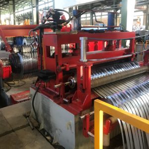
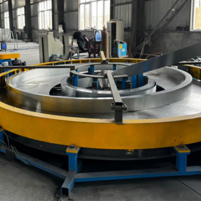
1. Coil Charging Car:
Structure Type:
Double sided 180º rotary hydraulic expansion system, designed for secure and stable clamping of steel coils on both mandrels. This mechanism allows automatic alternation between two coil stations, ensuring continuous coil feeding without interruption. The 180º rotation enables one mandrel to load or unload while the other is actively feeding material, optimizing production efficiency.
The hydraulic expansion applies uniform radial pressure to hold the coil tightly, preventing slippage during unwinding. This setup ensures smooth, controlled feeding of the steel strip into the accumulator, reducing tension fluctuation and material deviation during high speed operation.
The system is compatible with steel coils having an:
• inner diameter of 610–760 mm
• outer diameter of 1100–2100 mm
and supports a
• maximum load of up to 8000 kg.
It is designed to handle
• strip widths ranging from 60 to 240 mm
offering flexibility for different production needs and coil sizes.
2. Shear And Butt Welder:
Shearing and butt-welder, which insure double steel tidily and then welding and
leveling weld seam and supply strips for accumulator.
| Item | Description |
| Function | Cut off defective parts at the beginning, end, and middle of the steel strip – Cut head and tail before butt welding for straight alignment |
| Structure Type | Hydraulic shear + Wire-feed welding |
| Shear Thickness | ≤3.65 mm |
| Max Cutting Width | 240 mm |
| Remark | Moveable on the rail |
3. Horizontal Accumulator:
| Item | Description |
Main Composition | Used for storage, loading/unloading, and driving strip steel. Includes: power part, inner ring, middle roller, horizontal roller, outer ring stop roller, feeding stop roller frame, etc. Transmission system includes motor, reducer, and universal coupling. |
| Rollers | Vertical/Horizontal rollers made of seamless 45# steel pipe, quenched to HRC45–50° |
| Principle | – Pull-in from outside, discharge from center – Non-powered, pulled by the main machine’s force |
Accumulator Diameter | Φ5000mm |
| Strip Width | 60 mm ~ 240 mm |
| Strip Thickness | 2.50 mm ~ 3.65 mm (J55) |
Storage Capacity | 200 – 500 m |
| Motor Power | AC Motor, 30 kW |
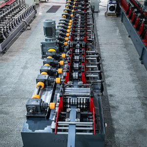
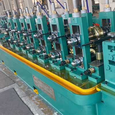
4. Forming Machine:
| Description | Item | Technical parameters |
Horizontal-roll stands | Quantity | Seven stands |
| Material of horizontal stands | High-precision forged steel | |
| Diameter of horizontal shaft | Φ80mm | |
| Material of horizontal shaft | 42CrMO | |
Vertical-roll stand | Quantity | seven stands |
| Material of vertical stands | QT50 | |
| Diameter of horizontal shaft | Φ50mm | |
| Material of horizontal shaft | 45# forged steel | |
Driven gearbox | Quantity | Seven gearboxes |
| Material of gearbox | QT50 | |
| Type | Spiral bevel gear | |
| Material of gearbox | 20CrMnTi | |
| Material of shaft | 40Cr | |
Power transmission method | From universal transmission joint to horizontal roll stands |
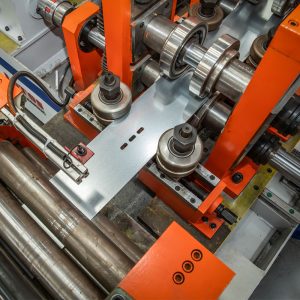
5. Roller Stands with Carriage System for Front Horizontal Stands in
Forming and Sizing Sections (easy change):
This system includes two sets of roller stands mounted on movable carriages (or
trolleys):
• One set for the Forming section
• One set for the Sizing section
These stands are installed on rails or wheeled carriages, allowing for smooth and
controlled movement of the roller assemblies.
Advantages:
1. Reduced roller changing time and increased production capacity:
With carriage-mounted roller stands, there’s no need for time-consuming manual disassembly.
The entire roller unit can be shifted easily, minimizing machine downtime and enhancing throughput.
2. Prevention of bearing damage and extended equipment lifespan:
In conventional setups, manually pulling out the roller frame can place excessive stress on bearings, leading to premature wear or failure.
The carriage system enables smooth and uniform movement, significantly reducing stress and potential damage to mechanical components.
3. Improved alignment and accuracy:
Carriage-mounted rollers can be positioned with high precision, ensuring better
alignment during tube forming and sizing processes.
Enhanced maintenance and safety:
Simplified access to the rollers facilitates maintenance and reduces the risk of worker injury
compared to manual frame handling.
1.1 Main Parameters:
• Rated Output Power: 300 kW
• Rated DC Voltage: 235 V
• Rated DC Current: 1500 A
• Overall Efficiency: η≈90%
• Output Frequency: 300–350 kHz
• Resonance Type: Compound Resonance
• Tank Circuit Output: No welding transformer output.
• Ripple Factor: < 0.5%
• Welding Method: Induction Welding
• Power Supply Capacity: 375 kVA
• Input Voltage: 3-phase, 380 V / 50 Hz, 4-wire system
• Rated Input Current: 569A
Cooling System (Soft Water Circulation – Air-Water Type):
• Operating Water Pressure: 0.32 MPa
• Water Flow Rate: 30 m³/h
• Cooling Capacity: 110 KW
2. System composition:
The solid state high frequency all-in-one welder consists of four main parts:
IGBT high frequency inverter with PWM voltage regulator,
High frequency transformer,
High-frequency rectifier using FRED fast recovery diode module,
E-bridge inverter output.
AC voltage regulation with PWM is integrated into a single control board. The PWM control
unit is embedded on the main board, with its main functions managed by a single-chip
microcomputer and PWM control system. Voltage adjustment and feedback control are
achieved through the dual closed loop PI regulator on the main board.
Alarm and protection control are based on a digital circuit as the control core, combined with
fast response hardware, ensuring sensitive and precise protection actions.
This welder uses a full-wave rectification and IGBT inverter regulation mode, eliminating the need for phase angle control used in older systems. As a result, it offers high power factor,energy saving performance, and reduces the cross sectional area required for input cables.
Solid state HF welder is designed for continuous working. Rectifier inverter integrated structure, compact size easy to install. The whole set of equipment achieves the function of equipment linkage control and diagnosing faults by PLC system. The working statue is observed by LCD display.
Inverter adopts E bridge structure. The main power parts are IRFP460 from IR Company
and DSEI60-06A fast recovery diode from IXYS Company in US, which are composing current inverter.
The output power of single layer power module is 50KW, the equipment are parallel connected by multilayer power modules. The rated work frequency is 400KHz. The same power module is interchangeable. This power module can work steadily in 600KHz,
therefore it can work in 400KHz easily. The technique of the equipment is well proven.
3. Performance and Efficiency Gains with IGBT Inverter Technology:
1. High Energy Efficiency:
IGBT modules offer low switching losses, enabling system efficiency greater than 90%.
2. Stable Output and Consistent Weld Quality:
Precise voltage and frequency regulation via PWM ensures steady operation and uniform weld seams.
3. High Power Factor and Reduced Energy Consumption:
The use of full wave rectification and elimination of phase-angle control significantly improves power factor and reduces electrical losses.
4. Compact System Design:
IGBT inverters eliminate the need for bulky phase-control components, resulting in a more compact and space-saving layout.
5. Reduced Input Cable Size:
Due to stable current draw and improved power factor, smaller input cables can be used, lowering installation costs.
6. Enhanced Reliability and Low Maintenance:
Solid-state construction with no moving parts increases operational life and minimizes maintenance requirements.
7. Advanced Digital Protection Compatibility:
Fully compatible with fast response digital protection systems, ensuring precise fault detection and improved operational safety.
4. Main Components List:
| Name | Model | Manufacturer |
| IGBT | FF450 | Infineon |
| Quick recovery diode | DSEI60 | IXYS Co. IXYS |
| Resistance | 25R | Austria |
| Tank circuit capacitance | CS | Domestic famous brand |
| PLC | SR30 | |
| Human interface | Kunluntongtai | |
| Switch power supply | Taiwan Minwei Co. | |
| Air-Cooling System | FS series F-S | Domestic famous brand |
5. Scraper Frames:
Function:
Two sets of scraper frames are installed to remove the external weld bead formed
after the HF welding process. This operation enhances surface quality and prevents interference in subsequent processes like coating or sizing.
Design Features:
• Each frame is equipped with an adjusting pole for precise positioning.
• Includes a quick feed-in and feed-out mechanism, allowing fast and efficient changeovers during production shifts.
• Facilitates easy maintenance and adjustment based on pipe diameter and
• weld bead profile.
| Item | Description |
| Welding Section Scope | Includes guiding device, 3-roller extrusion unit, weld scraping device, polishing unit, and cooling system. |
| Weld Guiding Device | Two-roller guiding mechanism used to center the weld seam precisely. |
| Extrusion Roller Device | Two-roller extrusion system – Rollers on both sides are motor-driven and adjusted via worm gear system. |
Scraping Device | Double-knife planing system – Can operate alternately or simultaneously – Blade change without stopping – Quick lift and movement (up/down & forward/backward) – Easy adjustment |
| Polishing Device | Flat roller used to polish the weld seam by applying pressure. |
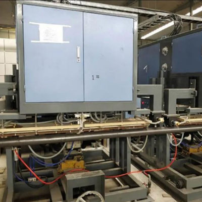
6. Medium Frequency Annealing Device (Online):
| Item | Specification |
| O.D of Round Tube | Φ21mm ~ Φ76mm |
| Round Tube Thickness | 2.50mm ~ 3.65mm |
| Annealing Temperature | 950 °C ± 50 °C |
| Temperature Accuracy | ± 4 °C |
| Heating Width | 25mm |
| Power | 2 × 300KW |
| Annealing Speed | 20 m/min ~ 80 m/min |
Equipment Composition | • IF rectifier inverter cabinet, 2 sets • Capacitance output cabinet, 2 sets • Center console, 1 set • Rocker arm button control box, 2 sets • Mobile trolley, 2 sets • Water-water cooling system, 2 sets • Cables between IF rectifier and inverter cabinets, 2 sets • Thermometer, 1 set • Gripping mechanism, 2 sets |
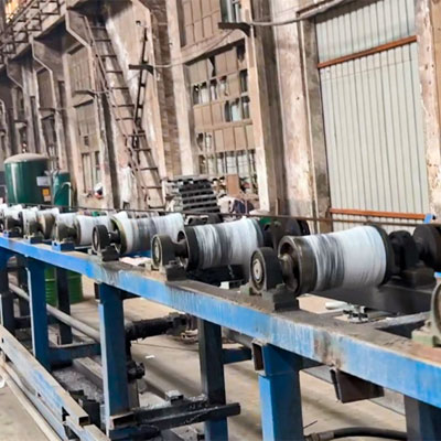
7. Air Cooling:
| Item | Description |
| Roller Table Length | 30 meters |
| Air-Cooled Roller Table | Active pull-out stable frame, driven by a 15KW motor |
| Function | Uses air cooling to reduce steel pipe temperature to room temperature |
8. Cooling type: Sink and shower:
| Item | Specification |
| Water Cooling Tank Length | 6 meters |
| Structure Type | Sink and shower installed in the machine bed |
| Function | Uses water cooling to reduce the steel pipe temperature to room temperature |
9. Sizing Machine:
| Description | Item | Technical parameters |
Horizontal-roll stands | Quantity | Seven stands |
| Material of horizontal stands | High-precision forged steel | |
| Diameter of horizontal shaft | Φ80mm | |
| Material of horizontal shaft | 42CrMO | |
Vertical-roll stand | Quantity | seven stands |
| Material of vertical stands | QT50 | |
| Diameter of horizontal shaft | Φ50mm | |
| Material of horizontal shaft | 45# forged steel | |
Driven gearbox | Quantity | Seven gearboxes |
| Material of gearbox | QT50 | |
| Type | Spiral bevel gear | |
| Material of gearbox | 20CrMnTi | |
| Material of shaft | 40Cr | |
Power transmission method | From universal transmission joint to horizontal roll stands |
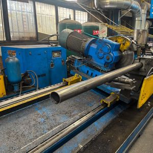
10. Cold Saw Automatic Tube Mill 76:
Depscrition:
The Cold Flying Saw is an advanced solution for highspeed HF welded tube and pipe production lines, enabling
continuous cold mechanical cutting without stopping the line or generating heat.
The cutting head, mounted on a linear guide and driven by servo or hydraulic actuators, synchronizes with the moving tube. A high-performance circular blade (alloy steel or carbide) then executes a precise cut before returning for the next cycle.
1. Basic data:
| material | Q195 Q235 SPCC |
| Cutting range | Round Pipes: Min Φ21mm ~ Max Φ76mm |
| Production speed | 100m/min( length 6 meter, dia.≤25mm) |
| Cutting length | 1500-99999mm |
| Length tolerance | ±1.5mm(speed diviation not more than 2%); |
| Operation height: | 750mm |
| Cutting burr height: | Max: 0.25mm; |
| Power supply: | AC380V、 3PH、 50HZ |
3. Mechanical system:
| Mechanical length | 5420*1380*1380mm( as per final drawing) | |
Motor list | Drive: 15KW | servo motor |
| feed: 2.9KW | servo motor | |
| saw: 15KW | servo motor | |
| Linear guide | Hiwin Chinese Taiwan | |
| Clamp | pneumatic | |
| Clamp block model | tape shape to avoid scratching the steel pipe | |
| Oil supply system | Auto oil filling | |
| Saw blade | High speed steel | |
| main shaft gearbox | Special made | |
| Gear rack | KH from Chinese Taiwan | |
| Cable protection | Drag chain | |
| Carriage protection | Safety bumpers for carriage are equipped at both ends | |
| Equipment document | User’s manual & electrical diagram |
3.1. The equipment base is equipped with inlet guide rollers (upper and lower, left
and right rollers), the front end of the clamp is equipped with auxiliary guide rollers,
and the final discharge position has idlers. All idlers help the parallel movement of
the pipe during the sawing process.
3.2. Both ends of the saw body are equipped with carriage safety buffers;
3.3. The saw blade is equipped with a steel brush device to remove iron filings on the saw blade when rotating;
3.4. Equipped with adjustable cooling spray pipeline to flush the impurities and iron
filings on the saw blade and clamping block;
3.5. Sawing method: saw blade and feed are adjustable, that is to say, the speed of the feed servo motor is variable, and the speed of the saw blade is variable, so that the utilization rate of the saw blade is greatly improved; and the saw blade wear protection system is provided.
3.6. Each equipment is equipped with high speed steel saw blade 350*Φ50*200T, the number of saw blades: 2 pieces.
3.7. Equipment painting: the main body of the frame is black, and the moving parts such as the saw cover are yellow.
11. End Facing and and Beveling Machine:
| Item | Specification |
| Clamping device | Round Pipes: Min Φ21mm ~ Max Φ76mm |
| Tube thickness | 2.50 – 3.65 mm |
| Tube length | 6 – 12 m |
| Coil material | Q235, Q355, GI |
| Beveling angle | 30° ~ 35° |
| Standard | API-5L |
| Workstations | 4 workstations (staggered position) |
| Motor | AC 15 kW × 2 sets |
| Productivity | 12 – 20 pcs/min |
| Remark | Flat head and chamfering will be done at the same time |
12. Hydro-static Testing Machine:
| Item | Specification |
| Tube length | 6 – 12 m |
| Max test pressure | 5 – 20 MPa |
| Pressure time | 5 seconds, programmable |
| Testing quantity (per time) | 6 pcs |
| Sealed form | PU radial seal |
| Test medium | Emulsion (or water for high-pressure test) |
| Low-pressure water filling | Filled using low-pressure pump |
| Pressurization method | Boosted using booster pump |
| Max thrust | 54 tons |
| Productivity | 10 – 14 pcs/min |