
Tube Mill Design
An efficient tube mill layout design is the foundation of a high-performance steel pipe manufacturing line. A well designed layout minimizes material handling, improves production efficiency, reduces maintenance downtime, and ensures consistent pipe quality throughout the manufacturing process.
Whether producing round, square, rectangular, or customized steel tubes, the arrangement of equipment plays a critical role in achieving stable production, accurate forming, and reliable welding performance.
At LOTOSFORMING, every tube mill production line is engineered according to the customer’s production capacity, pipe dimensions, material specifications, and factory space to maximize operational efficiency.
What Is Tube Mill Layout Design?
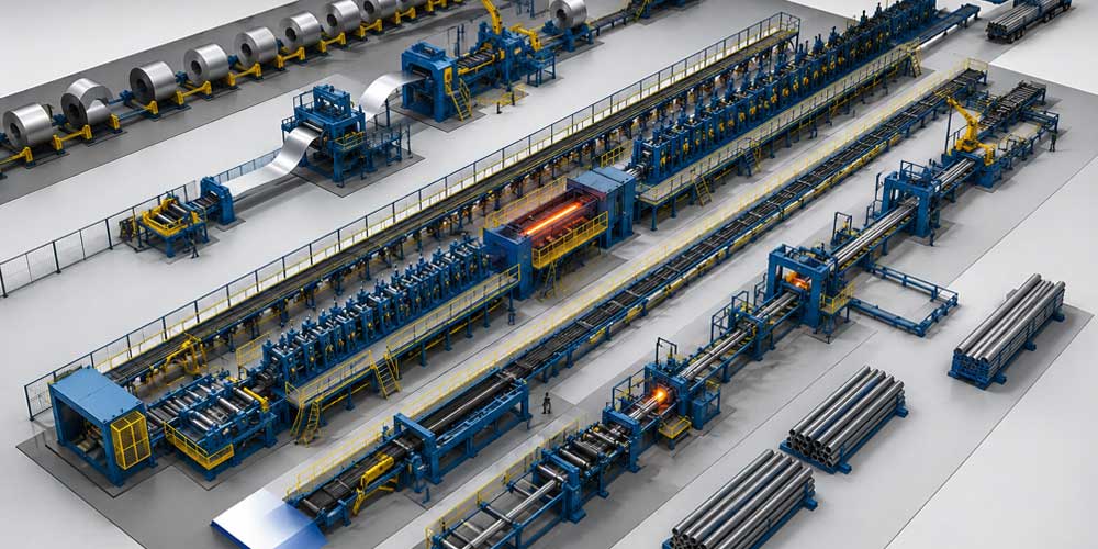
Tube mill layout design refers to the engineering process of arranging every machine and production station within a tube manufacturing line. The objective is to create a smooth, continuous production flow from steel coil loading to finished tube packaging while minimizing unnecessary movement and production interruptions.
A properly designed layout balances:
- Production efficiency
- Material flow
- Equipment accessibility
- Operator safety
- Maintenance convenience
- Future production expansion
Objectives of Tube Mill Layout Design
A professional tube mill layout should achieve several engineering objectives.
Continuous Material Flow
Steel strip should travel through the production line without unnecessary stopping or reversing, reducing production losses and improving throughput.
Stable Forming Process
Proper spacing between forming stands helps maintain strip stability during deformation, preventing edge buckling, wrinkling, and dimensional inaccuracies.
Efficient Power Transmission
The drive system should provide consistent torque to all forming stands through gearboxes, transmission shafts, and universal joints.
Easy Maintenance
Sufficient maintenance space allows engineers to replace rolls, inspect bearings, adjust stands, and service welding equipment safely and efficiently.
Basic Tube Mill Layout
A standard welded tube mill typically consists of the following sections:
Steel Coil
      │
Hydraulic Decoiler
      │
Strip Leveling
      │
Shear & End Welder
      │
Accumulator
      │
Forming Section
      │
HF Welding
      │
Weld Bead Removal
      │
Cooling Section
      │
Sizing Section
      │
Turks Head
      │
Flying Saw
      │
Run-Out Table
      │
Automatic Collection
Each section performs a specific function that contributes to the quality and productivity of the finished steel tube.
Decoiling Section
The production process begins with the hydraulic decoiler, which supports and unwinds the steel coil continuously.
Key functions include:
- Supporting heavy steel coils
- Maintaining constant strip tension
- Feeding strip into the leveling machine
- Preventing strip damage during unwinding
Modern production lines often include a coil loading car for faster coil replacement.
Strip Preparation
Before entering the forming section, the strip passes through several preparation stations.
These may include:
- Strip leveling
- Pinch rolls
- Shear and end welding
- Horizontal or vertical accumulator
The accumulator stores sufficient strip length to allow continuous production during coil changes.
Forming Section Layout
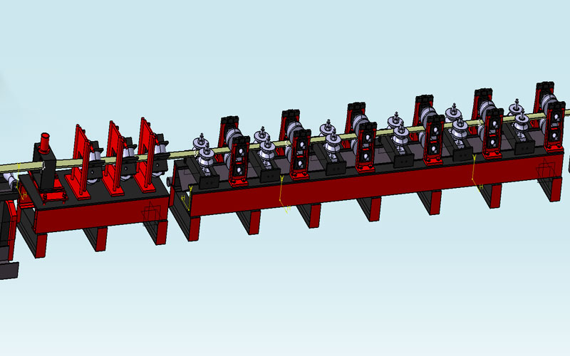
The forming section is the heart of every tube mill.
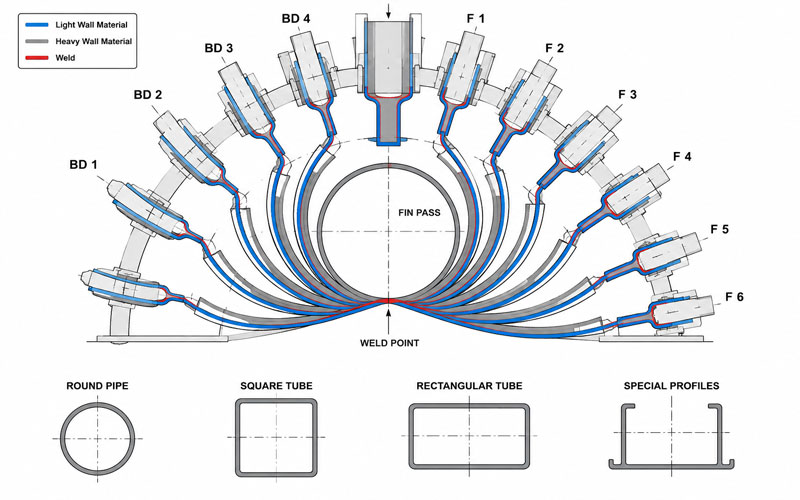
Here, multiple roll stands gradually bend the flat steel strip into a tubular shape.
Typical components include:
- Horizontal stands
- Vertical stands
- Universal stands (FFX systems)
- Guide rolls
- Side rolls
Each stand contributes only a small amount of deformation, minimizing material stress and improving tube accuracy.
Roll Stand Arrangement
Proper stand spacing is essential.
Factors affecting stand arrangement include:
- Tube diameter
- Wall thickness
- Material strength
- Production speed
- Forming technology
Modern FFX tube mills often utilize universal stands that allow multiple pipe sizes to be produced with minimal roll changes.
Drive System Layout
Power transmission is another critical aspect of layout design.
A typical drive system includes:
- Main motor
- Speed reducer
- Drive shafts
- Universal joints
- Gearboxes
- Roll shafts
Heavy duty tube mills frequently use individual gearboxes with spiral bevel gears to deliver stable torque to each forming stand.
High Frequency Welding Section
Once the strip edges meet, they enter the welding section.
This station generally includes:
- Guide rolls
- Squeeze rolls
- HF induction coil
- Impeder
- Weld box
Proper alignment ensures a strong, uniform weld seam while minimizing heat input.
Cooling Section
Immediately after welding, cooling equipment stabilizes the weld area and prepares the tube for sizing.
Efficient cooling:
- Reduces thermal distortion
- Improves dimensional stability
- Protects forming rolls
- Extends tool life
Sizing Section Layout
The sizing section accurately calibrates the tube dimensions.
It performs:
- Diameter correction
- Shape correction
- Straightness improvement
- Dimensional calibration
Depending on machine design, the sizing section may also convert round tubes into square or rectangular profiles.
Turks Head
The Turks Head provides final straightening before cutting.
Benefits include:
- Improved straightness
- Better surface appearance
- Reduced twist
- Higher dimensional consistency
Flying Saw Layout
The flying saw cuts continuously moving tubes without stopping production.
Advantages include:
- High cutting accuracy
- Increased production efficiency
- Smooth cut surfaces
- Minimal production interruption
Servo-controlled flying saw systems provide exceptional length accuracy at high production speeds.
Automatic Collection System
After cutting, finished tubes move to the run-out table for automatic collection, counting, bundling, and packaging.
Automation reduces labor costs while improving production efficiency.
Factors Influencing Tube Mill Layout Design
Several engineering factors influence the final layout.
Pipe Dimensions
Larger tubes require:
- Longer forming sections
- Larger roll stands
- Higher motor power
- Stronger drive systems
Material Type
Different materials require different forming characteristics.
Examples include:
- Carbon steel
- Stainless steel
- High strength steel
- Galvanized steel
Each material affects roll design, welding parameters, and stand configuration.
Production Speed
High-speed production requires:
- Precision roll alignment
- Stable strip guidance
- Efficient cooling
- Accurate flying saw synchronization
Factory Space
Available floor space determines:
- Line orientation
- Equipment spacing
- Maintenance access
- Future expansion possibilities
Modern Tube Mill Layout Trends
Modern manufacturing increasingly incorporates advanced technologies.
These include:
- PLC automation
- Servo-controlled adjustment
- Digital monitoring
- Online quality inspection
- Predictive maintenance
- Smart factory integration
These innovations improve productivity while reducing operating costs.
Common Layout Design Mistakes
Poor layout planning can lead to:
- Strip instability
- Frequent downtime
- Poor welding quality
- Difficult maintenance
- Increased energy consumption
- Low production efficiency
Professional engineering design helps eliminate these issues before installation.
Why Choose LOTOSFORMING?
LOTOSFORMING specializes in designing and manufacturing customized tube mill production lines for customers worldwide.
Our engineering team provides:
- Customized tube mill layouts
- High-speed production solutions
- FFX and Direct Forming technology
- Precision roll design
- Complete automation systems
- Installation and commissioning support
- Technical training
- Long-term after-sales service
Every production line is optimized for maximum efficiency, stable operation, and long service life.
Conclusion
A well planned tube mill layout design is essential for achieving high productivity, precise tube dimensions, and reliable long-term operation. From the decoiler to the automatic collection system, every station must be carefully engineered to ensure smooth material flow, efficient power transmission, and superior product quality. By combining advanced engineering, optimized equipment arrangement, and intelligent automation, manufacturers can significantly improve production performance while reducing operating costs. LOTOSFORMING delivers customized tube mill layout solutions tailored to meet the evolving demands of modern steel pipe manufacturing.
FAQ:
The forming section gradually transforms the flat steel strip into a tubular shape using a series of precisely arranged roll stands before the welding process.
Yes. LOTOSFORMING designs customized tube mill layouts based on customer requirements, including pipe dimensions, production capacity, factory layout, and automation level.
Proper equipment alignment and material flow help maintain accurate tube dimensions, improve weld quality, reduce strip deformation, and produce straight, high-precision tubes.
A typical tube mill layout includes a decoiler, strip leveling, shear and end welder, accumulator, forming section, welding unit, cooling section, sizing section, flying saw, run-out table, and automatic collection system.
A well-designed layout improves production efficiency, reduces downtime, minimizes material waste, enhances operator safety, and ensures consistent tube quality.