
A Technical Guide to ERW Tube Mill Tooling
In an ERW (Electric Resistance Welded) tube mill, the quality of the finished tube depends heavily on the roll design. Machine rigidity, drive power, and welding technology all matter. However, the tooling determines how a flat steel strip is progressively transformed into a closed, round (or shaped) section with a consistent weld seam.
Poor roll design leads to edge waves, weld seam misalignment, ovality, surface scratches, premature roll wear and excessive scrap. Sound roll design delivers stable production, longer tooling life and dimensional accuracy across the full range of sizes.
What Is Tube Roll Design?
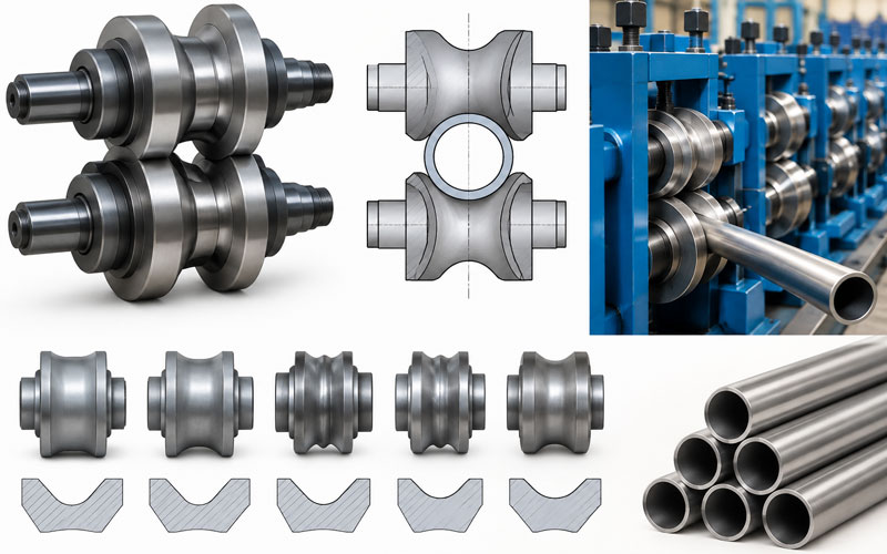
Tube roll design is the engineering process of defining the shape, diameter, sequence and clearance of each set of rolls through which the strip passes in a tube mill. The objective is to form the strip gradually, without overstraining the material, until the two edges meet precisely at the weld point.
A complete tube mill roll set generally covers four zones:
- Breakdown section: the strip begins to take shape and the edges are prepared.
- Fin pass section: the edges are brought to the correct form and presented to the welder.
- Welding and squeeze section: the edges are fused and forged together.
- Sizing section: the welded tube is calibrated to final diameter and straightness, often finished with a Turk’s head.
Each zone has distinct tooling requirements, and the whole sequence must be designed as a single system.
Key Stages of Tube Roll Design
1. Define the Product Specification
Design begins with the final tube requirements:
- Outside diameter (OD) and wall thickness (t)
- Tube shape (round, square, rectangular or special profile)
- Material grade and yield strength
- Dimensional tolerance and surface requirements
- Applicable standard (for example, structural, mechanical or API pipe)
The ratio of thickness to diameter (t/D) is particularly important. Thick-walled and high-strength tubes need more gradual forming and more robust tooling than thin-walled products.
2. Calculate the Strip Width
The strip width must be accurate. If it is too narrow, the edges cannot be properly welded. If it is too wide, excess material causes poor weld geometry and forming instability.
For round tube, the width is commonly estimated from the neutral-axis circumference:
W ≈ π × (OD − t)
This is only a starting point. The final width should include allowances for weld upset, edge condition and the characteristics of the material. These are normally refined through trial runs.
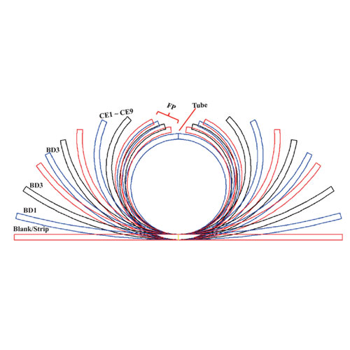
3. Develop the Flower Pattern
The flower pattern is a series of cross-section drawings showing the strip shape at each forming pass. It is the foundation of the roll design. A good flower pattern ensures that:
- Material is bent progressively, avoiding sudden strain.
- Edge elongation stays within safe limits, preventing edge waves and cracking.
- The strip remains stable and centered throughout the mill.
- The edges arrive at the weld point parallel and correctly aligned.
4. Select the Forming Method
Common forming approaches include:
- Edge forming (edge bending): the edges are formed first, then the centre of the strip. This is widely used for good edge control.
- Center-break and W-forming: the strip is shaped from the centre outward, suitable for specific sizes and materials.
- Flexible forming technologies: systems such as FFX and Direct Forming Technology (DFT) reduce the number of roll sets required across a size range by using adjustable or shared forming principles.
The right method depends on the size range, material, production volume and the cost of changeover. Our ERW Tube Mill Line, FFX Tube Mill Line and Direct Forming Technology pages describe these approaches in greater detail.
5. Design the Fin Pass Section
The fin pass stage is the most critical part of the mill. Fin pass rolls close the open seam gradually and deliver the edges to the weld point in a precise, parallel condition. Careful design should consider:
- Fin blade geometry and edge pressure
- Gap between the rolls at the seam
- Centering of the strip, which avoids one edge leading the other
- Smooth transition into the squeeze rolls
Errors at this stage appear directly as weld defects such as cold welds, offset edges or excessive bead.
6. Design the Welding Squeeze and Sizing Sections
Squeeze rolls apply controlled pressure to forge the heated edges together. The sizing section then brings the tube to final OD and roundness. Proper design here ensures:
- Consistent weld upset
- Accurate final diameter
- Good roundness and straightness
- Minimal residual stress
Sizing stands may be followed by a Turk’s head for straightening and for shaping square and rectangular sections.
Roll Materials and Heat Treatment
Roll tooling operates under high contact pressure and constant friction with the strip surface. Material selection therefore has a direct effect on tooling life and tube surface quality.
Commonly used materials include:
- Cr12MoV and D2 (SKD11) tool steels: high wear resistance, widely used for forming and sizing rolls.
- GCr15 bearing steel: commonly used for general-purpose applications.
- H13 hot-work steel: used where thermal resistance is required.
Rolls are generally heat treated to a working hardness in the range of about HRC 58–62, depending on the material and application. Precision grinding and, where required, surface treatments such as nitriding or chrome plating improve wear resistance and surface finish.
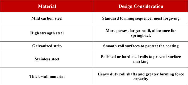
Roll material selection should be coordinated with the material being processed. For example, high-strength steel and coated strip place greater demands on tooling than mild steel.
Roll Design Considerations for Different Materials
Common Roll Design Defects and Their Causes
Many of these problems cannot be solved by adjusting the machine alone. They must be prevented at the design stage.
The Role of Design Software
Modern roll design commonly uses specialized software to develop and verify the flower pattern, calculate strip width, and simulate material behaviour before tooling is manufactured. Software such as COPRA RF and other roll forming design tools allows engineers to detect problems such as excessive strain or poor edge behaviour early, which reduces costly trial and error.
Software does not replace experience. Practical knowledge of materials, welding behaviour, and machine capability remains essential for a reliable design.
Quick Change Tooling and Roll Set Reduction
For manufacturers producing many sizes, tooling cost and changeover time become significant factors. Several strategies can help:
- Shared (universal) rolls: one roll set covers several sizes within a range.
- Cassette or quick-change stands: shorten changeover time.
- Flexible forming systems: reduce the number of dedicated roll sets.
These options should be evaluated against the expected product mix. A well-planned tooling strategy lowers total cost of ownership over the life of the line. Related topics are covered in our guide to Roll Forming Die and Processes.
Maintenance and Roll Life
Even an excellent design requires disciplined maintenance. Recommended practices include:
- Regular inspection of roll surfaces for wear, scoring and pitting
- Re-grinding rolls according to a defined schedule
- Maintaining correct roll gaps and alignment
- Proper lubrication and cooling during operation
- Storing roll sets in a clean, protected and organized way
A stable machine foundation also contributes to roll life and tube quality. See our article on How to Build a Foundation for a Tube Mill Line.
How LOTOS Forming Approaches Tube Roll Design
At LOTOS Forming, tube roll design is treated as an integrated engineering process. Our engineers consider the product specification, material, welding method, size range and production target together, rather than designing each pass in isolation. We offer:
- Customized roll design for each application
- Tube mill lines for ERW, FFX, API and DFT requirements
- Guidance on tooling strategy to balance cost and flexibility
- Installation, training and after-sales technical support
To discuss your tube specifications, please contact our team.
Conclusion
Tube roll design combines geometry, material science and welding knowledge. A properly developed flower pattern, a carefully engineered fin pass section, suitable roll materials and a rational tooling strategy together determine tube quality, productivity and operating cost. Investing in sound roll design at the outset reduces scrap, extends tooling life and ensures consistent results.