
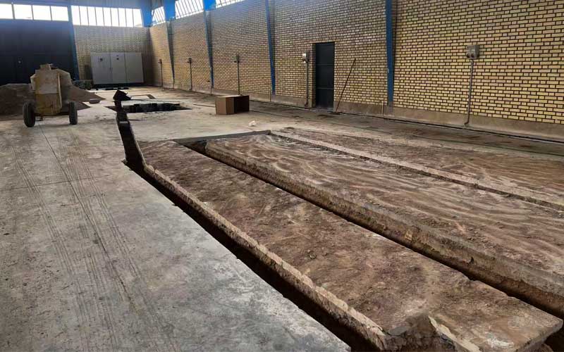
How to prepare the foundation for a tube mill ?
Installing a tube mill production line requires more than selecting the correct forming, welding, sizing, and cutting equipment. A properly designed and constructed foundation is essential for machine stability, production accuracy, vibration control, and long term operating reliability.
A tube mill line typically consists of multiple interconnected sections, including the decoiler, strip leveling and feeding equipment, forming mill, welding system, sizing section, cutting machine, run out table, and auxiliary equipment. Because these machines operate continuously and must maintain precise alignment, the foundation must be designed according to the actual machine layout, loads, operating conditions, and installation requirements.
This guide explains the main considerations for preparing a foundation for a tube mill production line.
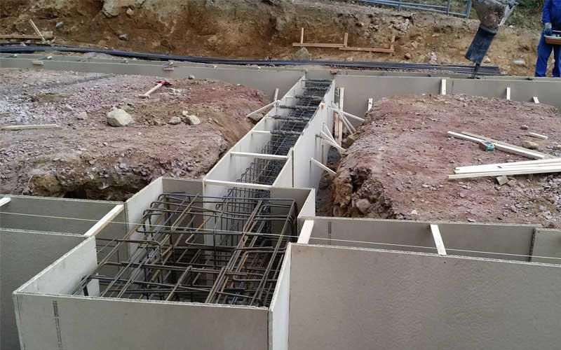
1. Why Is a Tube Mill Foundation Important?
A tube mill production line contains rotating rolls, motors, gearboxes, welding equipment, hydraulic systems, and cutting equipment. During continuous operation, these components generate static and dynamic loads.
A properly constructed foundation helps:
* Maintain accurate alignment between machine sections
* Support the weight of the production line
* Reduce vibration during high-speed operation
* Prevent foundation settlement
* Maintain forming and sizing accuracy
* Protect equipment from excessive mechanical stress
* Improve the service life of machine components
* Provide a stable reference for installation and commissioning
An inadequate foundation can cause machine movement, alignment problems, excessive vibration, premature component wear, and difficulties during commissioning.
2. Start With the Tube Mill Layout
The first step is to obtain the final tube mill production line layout from the machine manufacturer.
The foundation should not be constructed based only on the overall dimensions of the equipment. The exact positions of machine bases, anchor bolts, electrical cabinets, hydraulic units, welding equipment, and auxiliary systems must be considered.
A typical tube mill production line may include:
1. Coil loading and decoiling section
2. Strip leveling or straightening section
3. Strip accumulator or looper
4. Forming section
5. Welding section
6. Weld seam treatment
7. Sizing section
8. Straightening section
9. Cutting machine
10. Run-out table
11. Finished tube collection system
The foundation layout should correspond to the manufacturer’s approved installation drawing.
3. Determine the Foundation Load
Before concrete work begins, the required foundation load should be calculated based on the complete production line.
The calculation should consider:
* Machine weight
* Dynamic operating loads
* Motor and gearbox loads
* Coil weight
* Material accumulation loads
* Cutting forces
* Hydraulic equipment
* Auxiliary equipment
* Operator and maintenance loads
The manufacturer should provide the necessary equipment weights and foundation load requirements.
For heavy duty tube mills, dynamic loads can be particularly important. A foundation designed only for static machine weight may not provide sufficient stability during continuous high-speed production.
4. Check the Soil and Ground Conditions
The foundation design should also take the existing soil conditions into account.
Before construction, it is recommended to evaluate:
* Soil bearing capacity
* Groundwater conditions
* Existing concrete structures
* Soil settlement characteristics
* Underground utilities
* Drainage conditions
* Existing building foundations
For large or heavy tube mill lines, a professional structural engineer should determine whether the existing ground can support the required loads.
If the soil has insufficient bearing capacity, additional reinforcement, ground improvement, piles, or other structural solutions may be required.
5. Foundation Dimensions and Concrete Structure
The dimensions and depth of the foundation should be determined according to the machine manufacturer’s requirements and the site conditions.
A typical foundation structure may include:
* Reinforced concrete
* Reinforcing steel bars
* Embedded anchor bolts or anchor assemblies
* Machine mounting plates
* Leveling points
* Cable and utility trenches
* Drainage provisions where necessary
There is no universal foundation thickness or concrete depth that applies to every tube mill. The final dimensions should be based on the specific machine model, equipment load, soil conditions, and structural engineering calculations.
This is particularly important for large-diameter and heavy wall tube mill production lines.
6. Reinforcement and Anchor Bolt Positioning
Reinforcing steel provides the concrete foundation with the required structural strength.
The reinforcement arrangement should follow the structural engineer’s design. Special attention should be given to areas supporting heavy machine sections and locations subject to dynamic loads.
Anchor bolts are equally important because they connect the tube mill equipment to the foundation.
The following points should be controlled carefully:
* Anchor bolt diameter
* Bolt position
* Bolt spacing
* Embedded depth
* Vertical alignment
* Thread protection
* Position relative to the machine centerline
Anchor bolt positions should be checked against the final machine foundation drawing before concrete is poured.
Incorrect anchor bolt positioning can significantly complicate machine installation.
7. Machine Centerline and Leveling
Tube mill production depends heavily on accurate alignment.
During foundation preparation, the main machine centerline should be established and clearly marked. Reference points should be maintained throughout construction and installation.
The foundation should provide suitable leveling surfaces or adjustment points so that the machine can be accurately positioned during installation.
After the concrete has cured, the installation team should verify:
* Foundation elevation
* Machine centerline
* Anchor bolt positions
* Levelness
* Mounting surface condition
* Distance between machine sections
Precision measurement equipment should be used for final installation and alignment.
8. Concrete Pouring and Curing
Concrete should be poured according to the approved structural design.
Before pouring, verify that:
* Reinforcement is correctly installed
* Anchor bolts are accurately positioned
* Embedded components are secure
* Cable trenches are correctly located
* Formwork is stable
* Foundation dimensions have been checked
After pouring, the concrete must be properly cured. The machine should not be installed or operated before the foundation reaches the required strength specified by the structural engineer and machine manufacturer.
Adequate curing helps reduce the risk of cracking, deformation, and premature settlement.
9. Vibration Control
Vibration control is particularly important for tube mill production lines operating at high speeds.
Sources of vibration can include:
* Forming rolls
* Motors
* Gearboxes
* Welding equipment
* Sizing rolls
* Cutting systems
* Rotating shafts
A rigid and properly engineered foundation helps minimize unwanted movement.
Where necessary, the foundation design may incorporate additional structural measures or vibration isolation according to the machine manufacturer’s requirements and site conditions.
10. Cable Trenches and Utility Connections
The foundation should be coordinated with the complete factory utility layout.
Before concrete construction, determine the locations of:
* Electrical cable trenches
* Control cables
* Hydraulic lines
* Cooling-water pipes
* Compressed-air lines
* Welding system connections
* Drainage channels
Leaving these requirements until after the foundation has been completed can result in additional construction work and increased installation costs.
A coordinated layout allows the tube mill to be connected efficiently after mechanical installation.
11. Installation of the Tube Mill on the Foundation
Once the foundation has reached the required strength, the machine can be moved into position.
A typical installation process includes:
1. Confirming foundation dimensions and elevation
2. Establishing the machine centerline
3. Positioning the main machine sections
4. Installing anchor bolts and mounting components
5. Leveling each machine section
6. Aligning forming and sizing stands
7. Connecting mechanical components
8. Connecting electrical and hydraulic systems
9. Checking the complete production line
10. Performing trial operation and commissioning
The alignment of each section should be checked relative to the complete production line rather than treating each machine independently.
12. Common Foundation Problems to Avoid
Several foundation-related problems can affect tube mill installation and operation.
Incorrect Foundation Dimensions
Using estimated dimensions instead of the manufacturer’s final foundation drawing can cause installation difficulties.
Incorrect Anchor Bolt Positions
Even small deviations can prevent machine bases from being installed correctly.
Insufficient Foundation Strength
An undersized or improperly reinforced foundation may experience cracking, settlement, or excessive vibration.
Poor Leveling
Uneven machine mounting can affect roll alignment and tube quality.
Insufficient Concrete Curing
Installing heavy machinery before the concrete reaches the required strength can damage the foundation.
Poor Utility Planning
Incorrect cable trench or pipeline locations can interfere with machine installation and maintenance.
Ignoring Dynamic Loads
The foundation must account for operating conditions, not only the static weight of the equipment.
13. Recommended Foundation Preparation Procedure
For a successful tube mill installation, the following sequence is recommended:
Site Survey → Soil Evaluation → Tube Mill Layout Confirmation → Foundation Load Calculation → Structural Design → Reinforcement → Anchor Bolt Installation → Concrete Pouring → Concrete Curing → Foundation Inspection → Machine Installation → Alignment → Commissioning
Close communication between the tube mill manufacturer, civil contractor, structural engineer, and installation team is essential throughout the process.
14. Foundation Requirements for Different Tube Mill Sizes
Not every tube mill requires the same foundation design. A compact tube mill for small-diameter tubes may have substantially different requirements from a heavy-duty line designed for large-diameter structural pipes.
Important variables include:
* Tube diameter range
* Strip thickness
* Steel grade
* Production speed
* Machine weight
* Forming stand configuration
* Welding system
* Cutting method
* Coil weight
* Factory floor conditions
For this reason, a standard foundation drawing should not be applied to a different tube mill without engineering verification.
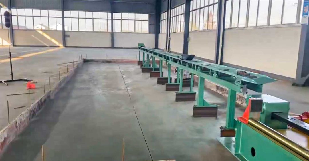
Conclusion
A reliable foundation is a critical part of a **tube mill production line**. Proper foundation design supports machine stability, accurate alignment, vibration control, safe operation, and long-term production performance.
The foundation should be designed only after the **complete tube mill layout, equipment loads, anchor bolt positions, utility requirements, and site conditions** have been confirmed. Working closely with the tube mill manufacturer and a qualified structural engineer can help prevent costly installation problems and ensure that the production line performs as intended.
LOTOSFORMING provides customized tube mill production lines and can supply the relevant machine layout and foundation requirements according to the customer’s tube specifications, production capacity, and factory conditions.
FAQ:
A rigid and properly engineered foundation helps reduce vibration. The design should consider dynamic loads generated by forming stands, motors, gearboxes, sizing equipment, welding systems, and cutting equipment.
Important information includes the tube diameter range, strip thickness, machine dimensions, total equipment weight, coil weight, production speed, machine layout, anchor bolt locations, dynamic loads, and site soil conditions.
The foundation should be designed by a qualified structural or civil engineer based on the tube mill manufacturer’s technical drawings and actual site conditions. The equipment manufacturer and engineering team should coordinate before construction begins.
There is no universal foundation depth for every tube mill. The required depth depends on the machine weight, production speed, dynamic loads, soil bearing capacity, equipment configuration, and structural design. The final foundation dimensions should follow the manufacturer’s foundation drawing and a qualified structural engineer’s calculations.
A professional tube mill manufacturer should provide the necessary foundation and installation information, including machine layout, equipment dimensions, anchor bolt locations, centerlines, and relevant load information, so the customer can prepare the factory foundation correctly.