
1. Overview of HF Welding in a Tube Mill
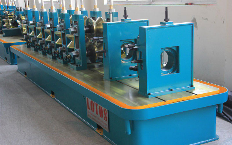
In a tube mill, flat steel strip is progressively formed by roll stations into an open, nearly circular profile. At the welding station, the two strip edges approach each other to form a V-shaped opening, known as the weld vee. High frequency current, typically in the range of 100 to 500 kHz, is supplied by an induction coil or sliding contacts and is directed along the edges of the vee toward the apex, where the edges meet.
The current heats the edges to forging temperature through electrical resistance. Squeeze rolls then press the molten, plastic edges together, forming a solid-state forge weld without filler metal. The process is fast, energy efficient and well suited to continuous production.
2. Two Electrical Phenomena Behind HF Welding
HF welding relies on two electromagnetic effects:
- Skin effect: at high frequency, alternating current flows in a thin layer near the surface of a conductor rather than through its full cross section.
- Proximity effect: when two conductors carry currents in opposite directions, the current concentrates on the facing surfaces. In the weld vee, the opposing edge currents are drawn toward the inner faces of the edges, which concentrates heat exactly where it is needed.
Together, these effects focus energy at the strip edges. However, the tube is a closed circular conductor, and the current has more than one possible path. This is where the ferrite impeder becomes essential.
3. The Problem: Unwanted Current Paths
When the induction coil or contacts apply voltage to the tube body, current does not travel only along the vee edges. A portion of it circulates around the inner circumference of the tube, on the shorter and lower-impedance path behind the vee. This is called the bypass or inner-loop current.
Current flowing through this path produces no useful heat at the weld point. The consequences include:
- Wasted power and lower welding efficiency
- Reduced heat at the vee edges, requiring a higher power setting
- Unnecessary heating of the tube body
- Unstable weld quality and a narrower process window
4. The Role of the Ferrite Impeder
The impeder is a bundle of soft ferrite rods placed inside the tube, beneath the welding area. Ferrite is a ceramic magnetic material that combines high magnetic permeability with high electrical resistivity. When the high-frequency field passes around it, the ferrite core increases the inductive impedance of the inner circumferential path.
In practical terms, the impeder makes the bypass path electrically unattractive. With the inner loop effectively choked, most of the current is forced to follow the lower-impedance path along the two edges of the vee to the weld point. The result is:
- Higher proportion of the supplied power converted into useful weld heat
- Reduced power consumption for the same tube size and speed
- More concentrated and consistent heating of the edges
- Better weld quality and a wider operating window
Because the ferrite does not carry current itself, it behaves as a magnetic flux concentrator rather than as an electrical conductor.
5. Construction of a Welding Impeder
A typical impeder assembly consists of the following parts:
- Ferrite rods: manganese-zinc or nickel zinc soft ferrite selected for high permeability and low loss at the operating frequency.
- Protective casing: a non-magnetic, heat resistant housing, often made of glass fibre reinforced material or stainless steel, that encloses and protects the rods.
- Cooling channel: a path through which coolant flows to remove heat from the ferrite.
- Support mandrel or rod: a non magnetic rod or cable anchored at the entry of the mill, which holds the impeder at a fixed position inside the moving tube.
The assembly must be slim enough to pass freely through the formed tube and rigid enough to remain stable under vibration and thermal stress.
6. Why Cooling Is Critical
Ferrite is subject to hysteresis and eddy-current losses in the high frequency field, and it is also exposed to heat radiated from the hot weld zone. Every ferrite material has a Curie temperature, above which it loses its magnetic properties. If the impeder overheats, its permeability collapses, the impedance of the inner path drops, and the bypass current returns.
For this reason, welding impeders are cooled by a continuous flow of clean water or emulsion, usually supplied through the mandrel. Effective cooling provides several benefits:
- It keeps the ferrite below its Curie temperature
- It reduces the risk of cracking caused by thermal shock
- It extends the service life of the rods
- It supports consistent weld quality throughout a production run
Coolant flow and temperature should be monitored, and any blockage or loss of flow should trigger an alarm or a line stop.
7. Positioning of the Impeder
Correct positioning is as important as correct selection. The principal guidelines are as follows:
- Longitudinal position: the impeder should extend from the region beneath the induction coil or contacts to a point close to, and normally slightly before, the centre line of the squeeze rolls. If it is too far forward, it may be damaged by the weld heat; if too far back, the choking effect is weakened.
- Radial clearance: the impeder should be centred in the tube, with the gap between the ferrite and the tube inner wall kept small, since a smaller gap generally gives a stronger impedance effect. The gap must remain sufficient for free passage and for the removal of the inner weld flash.
- Alignment: the assembly should be parallel to the tube axis and stable, without drifting or touching the strip edges.
Positioning is normally adjusted during setup and fine-tuned according to weld appearance, power consumption and tube speed.
8. Selection Criteria
When choosing an impeder for a given tube mill, the following factors should be considered:
- Tube outside diameter and wall thickness, which determine the available inner space
- Welding frequency and power rating of the HF generator
- Material being welded, such as carbon steel, low-alloy steel or stainless steel
- Line speed and duty cycle
- Cooling capacity available on the mill
An impeder sized for one tube diameter should not be used indiscriminately across a wide range of sizes. A properly matched ferrite cross section is required for each tube size range.
9. Maintenance Recommendations
To maintain stable operation and extend the service life of the welding ferrite, the following practices are recommended:
- Inspect the ferrite rods and casing at every roll change or scheduled stop for cracks, chipping and discoloration.
- Verify coolant flow, pressure and cleanliness, and replace or filter the coolant as necessary.
- Check the support mandrel for straightness and secure anchoring.
- Keep the weld area free of scale and spatter, and ensure the inner flash removal is functioning correctly.
- Record power consumption at a reference tube size; a gradual increase is often the first sign of impeder degradation.
- Store spare impeders in a dry, protected location to avoid mechanical damage.
11. Conclusion
The ferrite impeder is a compact component with a decisive effect on HF tube welding. By raising the impedance of the inner circumferential path, it directs the high frequency current to the strip edges, improving heating efficiency, energy economy, and weld consistency. Correct selection, accurate positioning, reliable cooling and disciplined maintenance are the conditions under which it performs as intended.
Lotosforming designs and manufactures complete tube mill lines, together with the roll tooling, welding systems and auxiliary equipment that support them. To discuss your tube size range, material and output requirements, please contact the Lotosforming team for a tailored technical proposal.
FAQ:
No. It acts as a magnetic flux concentrator and does not conduct the welding current.
Service life depends on tube size, power level, cooling and operating conditions. Replacement should be based on regular inspection and monitoring of power consumption and weld quality rather than on a fixed interval.
It is a ferrite-core impeder installed inside the tube at the weld zone to increase the impedance of the inner current path and concentrate high-frequency current at the strip edges.
To keep it below its Curie temperature, prevent cracking from thermal shock and maintain its magnetic performance.