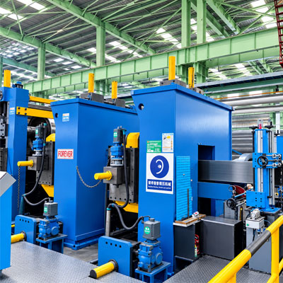
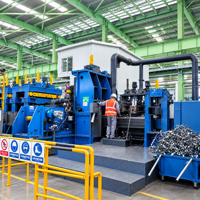
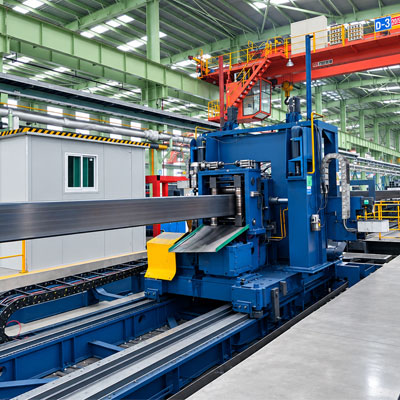
Product description
Working Flow :
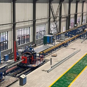
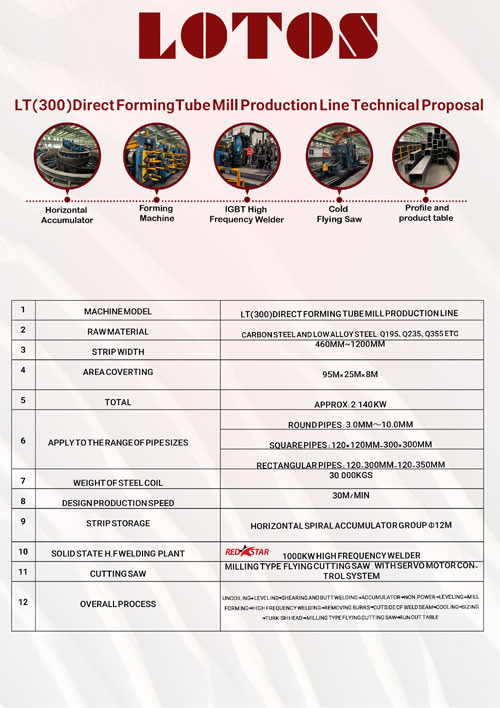
Raw material (steel coil) → uncoiling → leveling → shearing and butt-welding → horizontal accumulator → non-power leveling → mill-forming → high-frequency welding → removing burrs outside of weld seam → cooling → sizing → Turkish head → milling type flying cutting saw → run-out table
1. Coil Loading Cart | ||
1.1 | Loading capacity | 30,000kgs |
1.2 | I.D. of steel coil | Φ610-Φ760mm |
1.3 | O.D. of steel coil | Φ1300mm-Φ2100mm |
1.4 | Width of strips | 460mm~1200mm |
1.5 | Coil trolley travelling | Driven by AC motor |
1.6 | Coil trolley lifting | Hydraulic drive |
1.7 | Function | Used to transport the steel coils on the coil platform to the decoiler. |
1.8 | Equipment composition | It consists of V-type stand-by coil platform, cart body, traveling mechanism, supporting rollers, oil cylinders, guide rails, etc. |
2. Gantry Type Double Cone Decoiler | |||
2.1 | Maxi. load weight | ≤30,000kgs | |
2.2 | I.D. of steel coil | Φ610mm~Φ760mm | |
2.3 | O.D. of steel coil | Φ1300mm~Φ2100mm | |
2.4 | Width of strips | 460mm~1200mm | |
2.5 | Main body structure | Double cone head centering structure | |
Cone head expansion and contraction | Hydraulic drive | ||
Cone head rotation | Driven by hydraulic motor | ||
Brake | Hydraulic drive, adjustable | ||
2.6 | Press roller device | Press roller lifting | Hydraulic drive |
Press roller rotation | Driven by hydraulic motor | ||
2.7 | Shovel head device | Shovel head extension and retraction | Hydraulic drive |
2.8 | Straight head device | Straight head lifting | Hydraulic drive |
2.9 | Unwinding speed | 12m/min | |
2.10 | Total power | 4KW | |
1. Coil Loading Cart | ||
1.1 | Loading capacity | 30,000kgs |
1.2 | I.D. of steel coil | Φ610-Φ760mm |
1.3 | O.D. of steel coil | Φ1300mm-Φ2100mm |
1.4 | Width of strips | 460mm~1200mm |
1.5 | Coil trolley travelling | Driven by AC motor |
1.6 | Coil trolley lifting | Hydraulic drive |
1.7 | Function | Used to transport the steel coils on the coil platform to the decoiler. |
1.8 | Equipment composition | It consists of V-type stand-by coil platform, cart body, traveling mechanism, supporting rollers, oil cylinders, guide rails, etc. |
3. Leveling Unit | ||||
3.1 | Centering device | Hydraulic adjustment | ||
3.2 | Pinch device | Upper pinch roller | Can move up and down, driven by AC motor | |
Pressing down/lifting of upper pinch roller | Hydraulic drive | |||
Lower pinch roller | Fixed | |||
3.3 | Leveling roller device | 5-roller leveling | ||
Upper leveling roller | 2 pcs, can move up and down, driven by AC motor | |||
Pressing down/lifting of upper leveling roller | Hydraulic drive | |||
Lower leveling roller | 3pcs, passive | |||
3.4 | Leveling speed | 9m/min | ||
3.5 | Total power | 37KW | ||
4. Shear and Butt-welder | |||
4.1 | Function | l When the head of steel strip enters into the shearing part of the machine, the head of the strip is aligned with the center line of the tail of the previous steel strip, and then the irregular part of the head of the strip to be cut is sent to the shearing place, just overlapping with the cut tail, and then cut and start automatic welding. l After the automatic welding is completed, the whole system is reset and waits for the next working cycle. | |
4.2 | Structure | It consists of machine basement, 2 sets of centering device, automatic shearing device, automatic welding device, pinch device, etc. | |
4.3 | Centering device | Centering device movement | Driven by hydraulic motor |
Centering device clamping | Hydraulic drive | ||
4.4 | Hydraulic shearing device | Shear lifting and lowering | Hydraulic drive |
Shear blade clamping | Hydraulic drive | ||
Tilt angle | Designed according to strip specifications | ||
Shear blade material | H13 | ||
4.5 | Automatic welding device | Type | MAG, CO2 gas shielded welding |
Welding device movement | Hydraulic drive | ||
Weld seam adjustment | Mechanical | ||
Number of welding gun | 1 unit | ||
Welding gun movement | Driven by AC motor | ||
Welding plate clamping | Hydraulic drive | ||
4.6 | Pinch device | Upper pinch roller | Passive, movable |
Lower pinch roller | Active, fixed, AC motor drive | ||
Upper pinch roller pressing down and lifting | Hydraulic drive | ||
4.7 | Other specifications | Shear thickness | ≤10.0mm |
Maximum cutting width | 1200mm | ||
Working cycle | Max. 7min | ||
4.8 | Total power | 49KW | |
5. 11M Horizontal Accumulator | ||||
5.1 | Entry steering device | Roller type | Passive | |
Roller material | 45# steel | |||
5.2 | Feeding pinch device | l One mobile roller, one fixed roller, single roller active, AC motor, variable frequency speed regulation l Clamping and opening of mobile pinching roller: hydraulic drive l Pinching roller material: 42CrMo | ||
5.3 | Storage system | External in and internal out, fixed circle type, centralized transmission | ||
5.4 | Outer cage | Horizontal roller: active, centralized transmission, AC motor, variable frequency speed regulation | ||
Vertical roller: passive | ||||
5.5 | Inner cage | Horizontal roller, passive + partially active | ||
Vertical roller: passive | ||||
5.6 | Transition roller or plate between inner and outer cages | Type: passive | ||
5.7 | Center spiral material channel | Roller type: passive | ||
5.8 | Exit steering device | Roller type: passive | ||
5.9 | Hydraulic system | Pressure | 7Mpa | |
- 9. Sizing Machine
9.1
Function
Directly form to be square tube
9.2
Requirements
Square tube range: 120×120mm-300×300mm, T=3.0-10.0mm;
Rec. tube range: 120×130mm-300×350mm, T=3.0-10.0mm.
9.3
Roller groups
Universal stands, 4 stations
9.4
Shaft dia.
H:Φ210mm/SV:Φ110mm
“H”represents horizontal (roller shaft);
“SV”represents side vertical (roller shaft).
9.5
Shaft material
42CrMo/40Cr
9.6
Transmission shaft
SWC industrial coupling
9.7
Stands material
Q345B steel welding annealing treatment
9.8
Adjust type
Electrical adjustment, no need to change rollers (FFX)
9.9
Power transmission
From universal transmission joint to horizontal roller stands
9.10
Driven gearbox
Quantity
4 gear boxes
Material of gearbox
Q345 steel welding, annealing
Gear type
Spiral bevel gear (umbrella type)
Material of gear
20CrMnTi
Modulus
16 teeth
9.11 | Sizing machine layout | U, U, H(rebound), U, V(rebound), U, speed measuring roller, 2 Turkish heads; “U”represents universal stands; “H(rebound)”represents rebound horizontal stands; “V(rebound)”represents rebound vertical stands. |
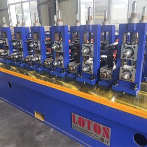
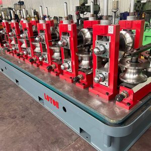
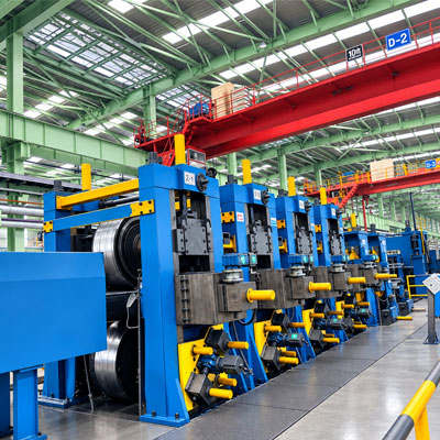
6. Mill-forming Machine | ||||
6.1 | Feeding guide | Leveling device | l 5-roller leveling, non-power l Shaft material: 40Cr l Adjust type: hand wheel rotation | |
Guide vertical rollers | 2 units, manual adjustment | |||
Feeding device | 1 station | |||
6.2 | Requirements | Square tube range: 120×120mm-300×300mm, T=3.0-10.0mm; Rec. tube range: 120×130mm-300×350mm, T=3.0-10.0mm. | ||
6.3
| Roller groups | Horizontal stands | Universal stands | Vertical stands |
7 stations | 5 stations | 2 stations | ||
6.4 | Shaft dia. | Φ210mm | H:Φ210mm/SV:Φ110mm | Φ130mm |
6.5 | Shaft material | 42CrMo | 42CrMo/40Cr | 40Cr |
6.6 | Transmission shaft | SWC industrial coupling | ||
6.7 | Stands material | Q345B steel welding annealing treatment | ||
6.8 | Adjust type | Electrical adjustment, no need to change rollers (FFX) | ||
6.9 | Power transmission | From universal transmission joint to horizontal roller stands | ||
6.10 | Driven gearbox | Quantity | 12 gearboxes | |
Material of gearbox | Q345 steel welding, annealing | |||
Gear type | Spiral bevel gear (umbrella type) | |||
Material of gear | 20CrMnTi, carburizing and quenching | |||
Modulus | 16 teeth | |||
7. Guiding and Extrude and Scraper | ||
7.1 | Welding section range | Guiding device, 5-roller extrusion device, scraping welding device, polishing, cooling system |
7.2 | Guide roller | Composed of a V-shaped roller and a vertical roller |
7.3 | Squeeze roller device | Adopt 5-roller extrusion, the motor drives the worm gear to adjust the labor-saving mechanism |
7.4 | Polishing device | Use one leveling roller to polish the welded junction with rolling way |
7.5 | Outer scrap welding device | Double blade plane scar, can use alternately or together, don’t stop to change knife saw, can lift rapidly, and can be adjusted up/down, forward/ backward, easy for adjust |
8. Cooling System | ||
8.1 | Function | Cool the tube to normal temperature |
8.2 | Cooling method | Spray and water bath |
8.3 | Cooling material | Water or coolant liquid |
8.4 | Cooling system | Circulation Cooling |
8.5 | Cooling tank length | 8M |
9. Sizing Machine | |||
9.1 | Function | Directly form to be square tube | |
9.2 | Requirements | Square tube range: 120×120mm-300×300mm, T=3.0-10.0mm; Rec. tube range: 120×130mm-300×350mm, T=3.0-10.0mm. | |
9.3 | Roller groups | Universal stands, 4 stations | |
9.4 | Shaft dia. | H:Φ210mm/SV:Φ110mm “H”represents horizontal (roller shaft); “SV”represents side vertical (roller shaft). | |
9.5 | Shaft material | 42CrMo/40Cr | |
9.6 | Transmission shaft | SWC industrial coupling | |
9.7 | Stands material | Q345B steel welding annealing treatment | |
9.8 | Adjust type | Electrical adjustment, no need to change rollers (FFX) | |
9.9 | Power transmission | From universal transmission joint to horizontal roller stands | |
9.10 | Driven gearbox | Quantity | 4 gear boxes |
|
| Material of gearbox | Q345 steel welding, annealing |
|
| Gear type | Spiral bevel gear (umbrella type) |
|
| Material of gear | 20CrMnTi |
|
| Modulus | 16 teeth |
10. Turkish Head | ||
10.1 | Function | Used for rough straightening of steel pipes after sizing. |
10.2 | Turkish head | 3-roller type, 2 SETS |
10.3 | Function | l Can move up, down, forward and backward, rotate 360° through worm gear and worm gear; l Coupled with a labor-saving structure and motor adjustment, no need to change the rollers; l The lifting and lateral movement are adjusted by motors. |
11. Milling Type Flying Cutting Saw □300×300×10mm | ||
11.1 | Machine basement | Equipped with linear guides, drag chain brackets, buffers, etc. |
11.2 | Cutting saw structure | 4 rollers |
11.3 | Feeding system | l Profiling feed system l Profiling feed in rectangular coordinate system l Feed control: AC servo motor, servo drive, 2×1.8KW |
11.4 | Milling cutting saw | l AC servo motor, variable frequency drive, 2×22KW l Number of saw blades: 2 l Saw blade material: TCT carbide, Φ355/Φ400mm |
11.5 | Guide roller device | 4-roller guide, screw drive, electric adjustment |
11.6 | Clamp device | Clamping and loosening of the device: hydraulic drive |
11.7 | Transmission mechanism | Gear rack |
11.8 | Transmission control | AC servo motor, variable frequency control |
11.9 | Speed measuring roller device | l Speed roller lowering and lifting: pneumatic drive l Speed sensor: encoder |
11.10 | Hydraulic pump station | Pressure: 12MPa |
11.11 | Electrical system | l System composition: operation console, electric control cabinet l Equipped with human-machine interface HMI, motion controller, fieldbus communication, servo drive, remote diagnosis module |
11.12 | Cut length | 6-12M |
11.13 | Cut length accuracy | ±2.0mm |
11.14 | Total power | 144KW |
FAQ:
The machine is designed for large square and rectangular tubes, including profiles up to approximately 300 × 300 mm, depending on the final tube dimensions and material specifications.
Direct forming can reduce forming passes, improve production efficiency, simplify the line layout, and provide an efficient solution for manufacturing large square and rectangular tubes.
Yes. The line can be configured to produce different square and rectangular tube sizes according to the customer’s required product range.
The LT(300) can process suitable carbon steel and structural steel strips, with the exact material range determined by the selected machine configuration.