Product description
Rolling Shutter Bottom Machine
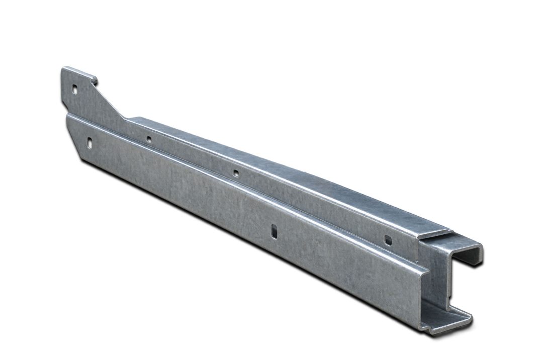
The bottom bar, also called the bottom rail or bottom retainer, is a cold formed steel section attached to the base of the garage door. It performs three main functions:
- Structural support: it keeps the bottom panel straight and rigid when the door opens and closes.
- Seal retention: its channel holds the rubber or vinyl seal against the floor.
- Installation interface: it provides a mounting point for brackets and fixings.
Because the bar is a visible, load bearing part of the door, it must have accurate dimensions and a clean surface finish.
How the Garage Door Bottom Bar Machine Works
The machine converts flat steel coil into finished bottom bars in one continuous process:
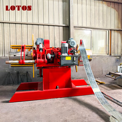
- Decoiling: the steel coil is loaded onto the decoiler and fed into the line.
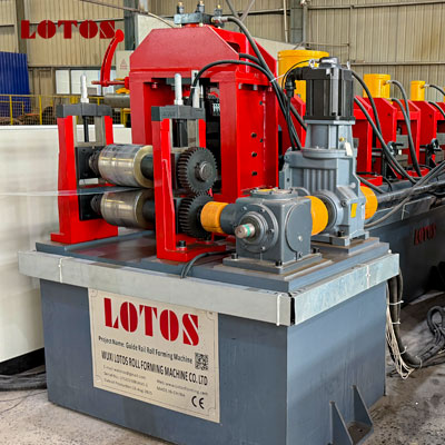
- Guiding and leveling: the strip is aligned so that it enters the forming section accurately.
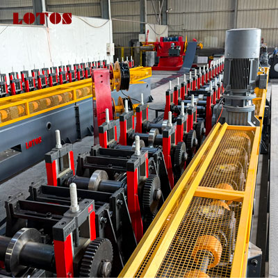
- Roll forming: a series of precision roller stations bends the strip step by step into the required profile.
- Cutting: a hydraulic cutting unit cuts the profile to the set length without stopping the line, or with a short stop, depending on the design.
- Run out: finished bars move onto the output table for inspection and packing.
An encoder measures the strip length, and the PLC system controls the cut. This gives repeatable length accuracy across each production batch.
Work Flow :
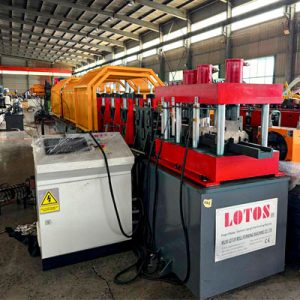
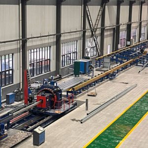
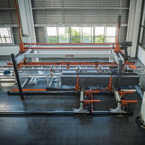
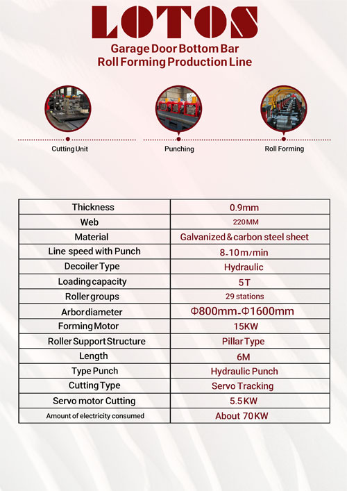
5T double head hydraulic decoiler→Shear & butt welder (purchased by Party A)→ Leveling + servo feeding + independent punching station + hydraulic cut-off →Pit→Forming main machine→Straightening device → Servo tracking cut-off → Pneumatic discharge table
Technical Parameters :
| 1.Double head hydraulic decoiler | ||
| 1.1 | Maximum load capacity | 5 tons per side (coil hung on one side) |
| 1.2 | Coil inner diameter | 18’’-20’’, inner diameter 24’’, using double-layer expanding segments |
| 1.3 | Coil outer diameter | Φ800mm-Φ1600mm |
| 1.4 | Cantilever length | 400mm per side |
| 1.5 | Function | l Electric uncoiling, hydraulic expansion, electric rotation |
| 1.6 | Remarks | l With cantilever l With disc brake l For small coils, with raising block l A drip tray is placed under the hydraulic power unit (see figure below) l Delta electrical components |
| 2. Shear & butt welder (purchased by Party A) | ||
| 2.1 | Function | l Cuts off the defective head and tail sections of the strip and the defective sections in the middle of the coil. l The head and tail are cut off before butt welding so that the weld seam is straight and aligned, which facilitates butt welding. |
| 2.2 | Structure | Hydraulic shearing + automatic welding |
| 2.3 | Shearing thickness | ≤2.0mm |
| 2.4 | Maximum cutting width | 250mm |
| 3. Independent punching station | ||
| 3.1 | Feed guide | Adjustable according to strip width; width adjusted via T-track |
| 3.2 | Leveling device | 2-roller feeding, 5-roller leveling |
| 3.3 | Servo feeding | 7.5KW, Delta |
| 3.4 | Punching dies | l 3 punching stations that must be adjusted individually l Y-axis manually adjustable, on both sides l Each die set must be equipped with 2 sets of feed guide wheels l 3 sets (punching layout; die design drawings must be provided) l Nameplate label with the punching diagram |
| 3.5 | Independent frame-type punching station | T-slot frame structure, plate thickness 60mm Dies are quick-insert type for easy replacement/maintenance One additional set of punch heads (spare parts) |
| 3.6 | Die material | CR12MOV, quenched |
| 3.7 | Others | Equipped with hydraulic pre-cut-off |
| 4. Forming Main Machine | ||
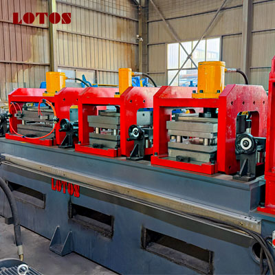
| 4.1 | Forming passes | 29 passes, pass center distance =18”(457.2mm) Initial forming 14 passes, fine forming 15 passes, built as 2 frame sections |
| 4.2 | Roller material | CR12MOV, quenched and tempered, heat treated, hardness HRC58-62°, mirror finish (A raw material quality report must be provided and samples will be inspected; if the material is found to be counterfeit, compensation of ten times the value will be paid) |
| 4.3 | Main shaft diameter | Main shaft diameter is 90mm (3.5”), with keyway (full-length keyway) |
| 4.4 | Main shaft material | 40CR, heat treated (quenched and tempered) (spacer sleeves must also have keyways) |
| 4.5 | Main motor | 11KW×2 units, Siemens Beide, with brake |
| 4.6 | Transmission | l 160# gearbox drive; a “LOTOS” header nameplate must be attached l Gear drive is added to the upper and lower shafts of every pass, on the same side as the gearbox l Sprockets are used to connect the gears and the gearbox |
| 4.7 | Frame structure | l 100*100*5mm square tube for the main frame structure, 6mm steel plate on the sides, with welded LOTOS nameplate; l Net frame height 725mm; center height of the strip exit above the floor 40’’ l Frame top plate: one-piece 25mm plate over the whole surface, precision machined l On the operator side, the base of the roll stand must be widened to 8’’=203.2mm, to make it easy to remove and place the roll stand |
| 4.8 | Roller structure | Uses 110# cast-iron roll stands, with a “LOTOS” pressing strip (customized by the roll stand manufacturer) |
| 4.9 | Forming speed | ≥15 m/min |
5. Cut off Section | ||
5.1 | Cut-off method | Servo tracking hydraulic cut-off |
5.2 | Servo motor | 5.5KW, Delta |
5.3 | Number of blades | 1 set with the machine, plus 1 set of spares |
5.4 | Die material | CR12MOV, quenched |
5.5 | Structure | Side-push type, refer to the video provided by the customer |
5.6 | Slide table requirements | T-track, 45mm specification Slide table length 2 m l Supplied by an independent hydraulic station, with accumulator, air-cooled |
5.7 | Cutting method | l Hole-counting cut-off, using a laser sensor l Minimum cutting length=36’’=914.4mm l Maximum cutting length=246’’=6248.4mm |
5.8 | Others | l The cable chain trough is on the same side as the machine drive |
FAQ:
A garage door bottom bar machine is a roll forming line that produces the bottom bar profile, also called the bottom rail or bottom astragal retainer. This profile is fitted to the lowest edge of a sectional garage door panel. It provides structural rigidity and holds the rubber weather seal in place. The machine uncoils, forms, cuts and delivers finished profiles in a continuous process.
The forming speed is 8–10 m/min. This speed supports stable profile accuracy and a consistent finish across the full length of the bottom bar. It also allows the cutting and auxiliary operations to be completed reliably.
We provide a warranty period for the main components, together with technical support and spare parts supply. Our engineers can offer training and troubleshooting guidance. Please contact us for the warranty terms that apply to your order.
The line is assembled and tested at our factory before shipment, so that installation at your site is straightforward. Installation time depends on your site conditions and the machine configuration. We can provide installation drawings, operation manuals and remote or on-site technical support to help you start production quickly.