Product description
What Is a Guide Rail Roll Forming Machine?
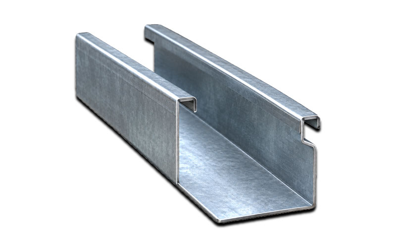
A guide rail roll forming machine is a continuous metal-forming production line that transforms flat coil material into guide rail profiles of a specified cross-section. The material passes through a sequence of forming stations, each with a matched pair of rollers that bends the strip a little further until the final profile is achieved.
Unlike press braking or stamping, roll forming is a continuous process. It allows long profiles to be produced in a single operation with excellent repeatability, and cutting, punching, and other processes can be integrated into the same line.
Typical profiles produced include:
- Sliding door guide tracks
- Rolling shutter and roller door guide rails
- Garage door track profiles
- Elevator guide rails (light-duty and auxiliary profiles)
- Drawer slide channels
- Window and curtain wall guide channels
- Shelving and storage system uprights and guides
Work Flow :
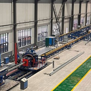
5T double-head hydraulic decoiler→Shear & butt welder (purchased by Party A)→ Leveling + servo feeding + independent punching station + hydraulic cut off →Pit→Forming main machine→Straightening device → Servo tracking cut off → Pneumatic discharge table
Technical Parameters :
| 1. Double head hydraulic decoiler | ||
| 1.1 | Maximum load capacity | 5 tons per side (coil hung on one side) |
| 1.2 | Coil inner diameter | 18’’-20’’, inner diameter of 24’’, using double-layer expanding segments |
| 1.3 | Coil outer diameter | Φ800mm-Φ1600mm |
| 1.4 | Cantilever length | 400mm per side |
| 1.5 | Function | Electric uncoiling, hydraulic expansion, electric rotation |
| 2. Shear & butt welder (purchased by Party A) | ||
| 2.1 | Function | l Cuts off the defective head and tail sections of the strip and the defective sections in the middle of the coil. l The head and tail are cut off before butt welding so that the weld seam is straight and aligned, which facilitates butt welding. |
| 2.2 | Structure | Hydraulic shearing + automatic welding |
| 2.3 | Shearing thickness | ≤2.0mm |
| 2.4 | Maximum cutting width | 250mm |
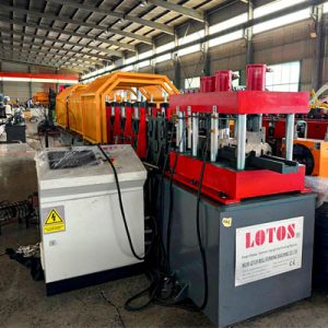
| 3. Independent Punching Station | ||
| 3.1 | Feed guide | Adjustable according to strip width; width adjusted via T-track |
| 3.2 | Leveling device | 2-roller feeding, 5-roller leveling |
| 3.3 | Servo feeding | 7.5KW, Delta |
| 3.4 | Punching dies | l 4 punching stations, individually adjustable l Y-axis manually adjustable, on both sides l Each die set must be equipped with 2 sets of feed guide wheels l 4 sets (punching layout; die design drawings must be provided) l Nameplate label with the punching diagram |
| 3.5 | Independent frame-type punching station | T-slot frame structure, plate thickness 60mm Dies are quick-insert type for easy replacement/maintenance One additional set of punch heads (spare parts) |
| 3.6 | Die material | CR12MOV, quenched |
| 3.7 | Others | Equipped with hydraulic pre-cut-off |
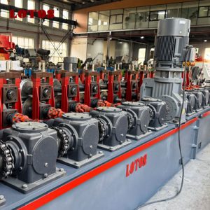
| 4. Forming Main Machine | ||
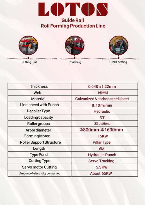
| 4.1 | Forming passes | l 23 passes, pass center distance =12’’=304.8mm l First pass with embossing |
| 4.2 | Roller material | CR12MOV, quenched and tempered, heat treated, hardness HRC58-62°, mirror finish (A raw material quality report must be provided and samples will be inspected; if the material is found to be counterfeit, compensation of ten times the value will be paid) |
| 4.3 | Main shaft diameter | Main shaft diameter is 90mm (3.5”), with keyway (full-length keyway) |
| 4.4 | Main shaft material | 40CR, heat treated (quenched and tempered) (spacer sleeves must also have keyways) |
| 4.5 | Main motor | 22KW, Siemens Beide, with brake |
| 4.6 | Transmission | l 160# gearbox drive; a “LOTOS” header nameplate must be attached l Gear drive is added to the upper and lower shafts of every pass, on the same side as the gearbox l Sprockets are used to connect the gears and the gearbox |
| 4.7 | Frame structure | l 100*100*5mm square tube for the main frame structure, 6mm steel plate on the sides, with welded LOTOS nameplate; l Net frame height 725mm; center height of the strip exit above the floor 40’’ l Frame top plate: one-piece 25mm plate over the whole surface, precision machined l On the operator side, the base of the roll stand must be widened to 8’’=203.2mm, to make it easy to remove and place the roll stand |
| 2.10 | Bearings | l Operator side – 22310CW33 spherical roller bearing l Gearbox drive side – 352212 double-row tapered roller bearing |
| 4.8 | Roller structure | Uses 110# cast-iron roll stands, with a “LOTOS” pressing strip (customized by the roll stand manufacturer) |
| 4.9 | Forming speed | ≥15 m/min |
| 5. Cut off Section | ||
| 5.1 | Cut-off method | Servo tracking type |
| 5.2 | Servo motor | 5.5KW, Delta |
| 5.3 | Number of blades | 1 set with the machine, plus 1 set of spares |
| 5.4 | Die material | CR12MOV |
| 5.5 | Structure | T-slot frame, 45° staggered cut |
| 5.6 | Slide table requirements | T-track, 45mm specification Slide table length 2 m Supplied by an independent hydraulic station, with accumulator, air-cooled |
| 5.7 | Cutting method | l Hole-counting cut-off, using a laser sensor l Minimum cutting length=36’’=914.4mm l Maximum cutting length=246’’=6248.4mm |
| 5.8 | Others | The cable chain trough is on the same side as the machine drive |
FAQ:
Common materials include galvanized steel, cold rolled steel, stainless steel, aluminum, and pre painted steel coils, within the thickness range specified for the machine.
Yes. Machines can be designed with adjustable stations or quick-change tooling to produce profiles of varying width or height within a defined range. Profiles with entirely different cross-sections generally require a separate roller set.
The forming speed is 8–10 m/min. This controlled speed supports stable forming, accurate punching, and precise cutting, which is particularly important for guide rails with complex cross-sections and tight tolerances.
A guide rail roll forming machine is a continuous production line that shapes flat metal coil into guide rail profiles through a series of progressive roller stations. It is widely used to produce tracks for sliding doors, rolling shutters, garage doors, windows, drawers, and storage systems.
The rollers are manufactured from high-grade alloy tool steel such as Cr12 or Cr12MoV, followed by heat treatment and precision machining. With proper maintenance and appropriate material, they provide a long service life.